Delivering the Ultimate Hardware Experience, Everytime
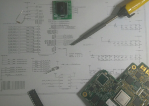
Board design always demands “Do it Right the First Time” simply due to the lack of the flexibility to modify/change/upgrade the design at a later stage or even after production, unlike the software. A Revision of PCB can cause huge delays in schedule and huge expenditure in proto builds, thereby missing the targeted Cost as well as Time-To-Market Window by an unacceptable Margin.
Simask’s Technologies’ Board / System Design Group believes in Correct By Construction Principle and has the capability to design and develop end to end products right from the concept till the production, abiding by the said Principle. The team has vast experience in high speed, high complex designs which involve several modules that are integrated to form a single product. The team has excellent exposure to develop products as per various regulatory / statutory compliance standards, inter alia, FCC, CISPER, CE, RTCA DO-160, MIL-461 and ISO26262. We also provide support in compliance testing at certified labs along with the final certifications / markings of the product as required. The team is capable of developing the Hardware using any industry standard tools like Cadence Orcad, Concept HDL, Altium, Allegro etc. We have tie-ups with several PCB Fabrication and PCB Assembly vendors and can take up the entire prototyping to any small/large scale manufacturing with a dedicated in house SCM (Supply Chain Management) team.
We offer swift product development for several industries like IoT (Internet of Things), Consumer Electronics, Industrial Automation, Wireless & Telecom, Defence and Automotive.
Our Services include broadly the following.
New Product Introduction (NPI)
• Concept, Architecture, Design Review and Consulting
• Component Benchmarking and BOM creation
• Circuit Design, Schematic Capture
Value Engineering
• BOM-optimisation, Form-Factor change
Maintenance & Support
• Production / Field Support, HW Failure Analysis
Prototype Development & Volume Manufacturing
• PCB Fabrication and Assembly through 3rd party tie-ups
• Dedicated SCM (Supply Chain Management) team to ensure smooth manufacturing / Assembly of PCBs
Board Bring up
• HW Diagnostics development
FPGA based design and development
Certification & Compliance as per standard requirements
Board Design: Complexity Snapshot
| Max. Layers | 32 |
| Max. Nets | 8500 |
| Max. Components | 5000 |
| Min. Trace width | 3 mils |
| Logic Families | SSTL, HSTL, LVDS etc., |
| Max. Frequency | 500 MHz |
| Max. IO Frequency | 25 Gbps |
| Max. Board dimension | 300 mm x 350 mm |
| Wattage | Few W to 150W |
| Max. BGAs per board | 28 |
| Max. Power supplies | 15 |
| PCB layout topology | With blind, buried vias, impedance matched |
| Component mix | Discrete, Logic, FPGA, ASICs, RF |
| Analysis | Timing, SI, Thermal, Power Integrity, Reliability, DFM |
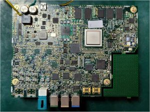 Development of the CPU Board for next generation ADAS / Infotainment solution for Chinese Tier 1 OEM
- Complete HW Architecture, Schematic Design, BOM Generation, Board Bringup & Validation
- Support for Manufacturing, Compliance testing
- 16 layer CPU Board
- TI Jacinto 6 (DRA756) based CPU Board design
- DDR3 (up to 4GB), EMMC (up to 32GB) , SD Card Interface
- Support for 4 different LCD Display modules (IVI, DIC, RV & HUD) through Serializers
- Support for 8 HD Camera (AVM, Face ID, DVR etc) and 4 Analog Camera
- Support options for 4G, WiFi, BT, USB Ports (3) with BC1.2Development of Management IO card for a Security Services Product (SSP) for US Networking Major
- SSP has 3 CPU Blades, 1 MIO Card, 1 Midplane, 2 redundant PSU & 4 redundant fans
- MIO card is based on Intel Quad core processor (Gladden) and PCH (Cavecreek). It also has 1.28Tbps Trident-II switch from Broadcom.
- MIO Interfaces to 3 CPU Blades through this Ethernet switch. On the Front panel, it supports two pluggable EPM slots and 8 fixed SFP+ ports. EPM cards support 8x10G or 4x40G ports.
- MIO card is 18 layer board with 10Gbps high speed signals all over the board
- Development of PSEQ SW for the complete MIO Card
- Design Verification test and Regulatory compliance tests as per FCC/CISPER standardsDevelopment of the complete In-Flight Entertainment Server according to ARINC600 4 MCU Module Standards for a European Avionics Major
- Modularized boards (CPU Board, IO Board, PSU Board & Backplanes)
- CPU Module (12 layer board)
- – Two enterprise grade SATA SSDs. One for OS / applications (32GB) and other for Video/Music Entertainment content (256GB to 1 TB)
- – 3x 7 Port Gigabit Ethernet Switches from Marvell (88E6351)
- – Provides 8 GigE (1 Front Panel, 1 CPU/IO board communication, 4 to Seat Display Unit, 1 Data Loading Port and 1 PoE port), 6 FE interfaces (to Backplane).
- – 3 HD Audio interface at Backplane and USB, UART and LEDs at the front panel.
- IO Board (12 layer board)
– IO Board is based on MPC8278E processor. It supports up to two DDR II memory chips in x32 configuration.
- – 3 ARINC 429 controllers in Local bus which support 6 Rx channels and 3 Tx channels
- – 8 ARINC 485 channels using two Quad UART controllers in SPI port
- – 16 Rx and 7 Tx ARINC 720 interfaces using IO Expanders in I2C port
- PSU board (6 layer board)
– Receives the 115V AC, 360 Hz to 800 Hz from source
- – Provides Input spikes protection and EMI filtering at AC side
- – AC/DC PFC section provides inrush protection, Power Factor Correction, High Voltage DC Conversion (300V). Output Capacitor provides steady DC o/p and hold up of up to 200ms
- – Provides 12V DC to CPU/IO boards through isolated DC-DC flyback converter with short circuit protection
- Backplane (8 layer board) Interconnects all the different boards (CPU, IO & PSU).
- Qualification of the unit as per RTCA DO-160E standards
- NPI of a 4G capable OBD-connected vehicle tracking device
- System architecture
- Component selection
- Schematic Design
- Board Bring-up & Diagnostics
- Complete S/W development
- Device Characteristics
– STM Cortex-M4 based main board
- – OBD control via ELM327
- – 4G module from QUECTEL
- – BT/WIFI module from QUECTEL
- – On-board accelerometer, gyroscope, pressure, temperature sensors
- – Li-Po battery charger and Fuel Gauge
- – PMIC with BUCK, Boost and LDOs
- – 2 board solution : 4-layer PCB
- – Mechanical (Plastic) Enclosure design (by partner)
- – Low Volume Production ramp by week 24
- SeNSe-IC™ Driver Assist Solution
- SeNSe-IC™ Sensor Fusion Solutions
- SeNSe-IC™ Machine Monitoring Solutions